


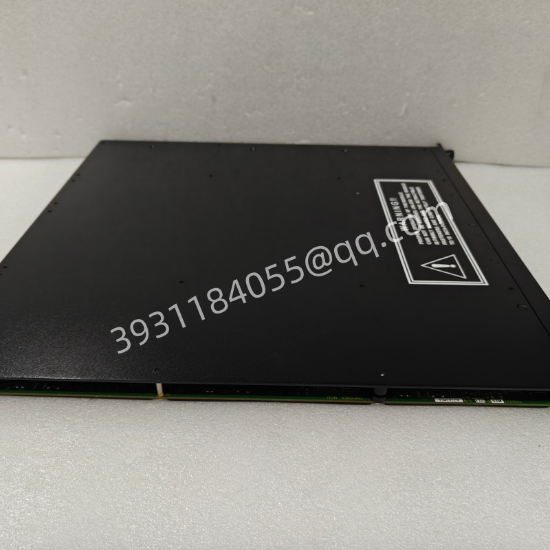
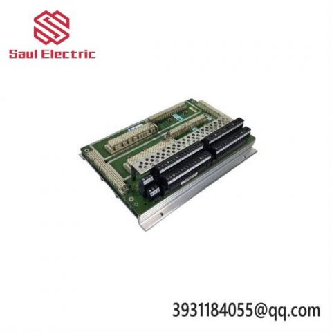
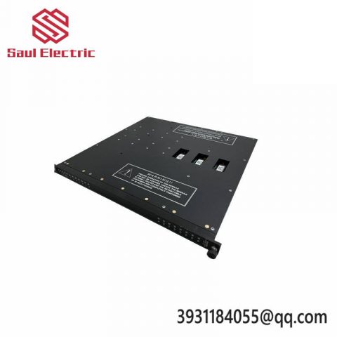
The Triconex 3504E is a 16 channel, 24V DC, Triple Modular Redundancy (TMR) digital output module in Schneider Electric’s (formerly Invision) Triconex Safety Instrumented System (SIS).
The suffix “E” in the model usually represents Enhanced. Compared to the basic version (such as 3504), 3504E provides more powerful diagnostic capabilities, higher reliability, and more flexible configuration options, designed specifically to meet the IEC 61508 SIL 3 safety level requirements. It is one of the standard output modules widely used in the Triconex V9 and V10 systems.
The following is a detailed technical analysis about 3504E:
1. Core functions and architecture
Triple Modular Redundancy (TMR):
The module contains three completely independent output channel circuits inside.
The main processor sends output instructions to these three channels, each of which independently drives the load.
If a channel detects its own fault (such as short circuit or open circuit), it will automatically disconnect, while the other two healthy channels will continue to maintain output, ensuring that the system does not stop (high availability) or enters a safe state according to a predetermined strategy.
Digital output (DO):
Used to control the switching actions of on-site equipment, such as solenoid valves, relays, indicator lights, motor starters, etc.
Supports sourcing output (usually module output+24V) or sinking output (specific order number suffix needs to be confirmed, 3504 series is mostly source type).
Enhanced Diagnosis (The “E” Factor):
Point by point diagnosis: capable of independently detecting the status of each channel.
Short circuit protection: When a short circuit to ground or power is detected, the channel will be automatically cut off and an alarm will be triggered to prevent damage to the module or power supply.
Open circuit detection: It can detect whether the load circuit is disconnected (depending on specific wiring or external resistance, depending on the specific configuration).
Over temperature protection: Monitor module temperature and automatically turn off output when overheated.
Field power monitoring: Real time monitoring of the external 24V power supply voltage supplied to the output stage.
2. Technical specifications (typical parameters)
Number of channels: 16 discrete output points.
Voltage level: 24 VDC nominal voltage (operating range typically 18-30 VDC).
Current capacity:
Single point maximum continuous current: usually ranging from 0.5 A to 1.0 A (depending on ambient temperature and heat dissipation conditions, please refer to the data manual for details).
Module total current: The sum of all channels is usually limited to around 8 A (requires derating for use).
Isolation:
The logic side (backplane) and the field side (field wiring) are isolated by photoelectric means.
Channels are usually grouped and isolated (e.g. every 4 or 8 channels) to limit fault propagation.
Response time:
The typical output response time is in the millisecond range (e.g.<10ms), meeting the needs of the vast majority of emergency shutdown (ESD) applications.
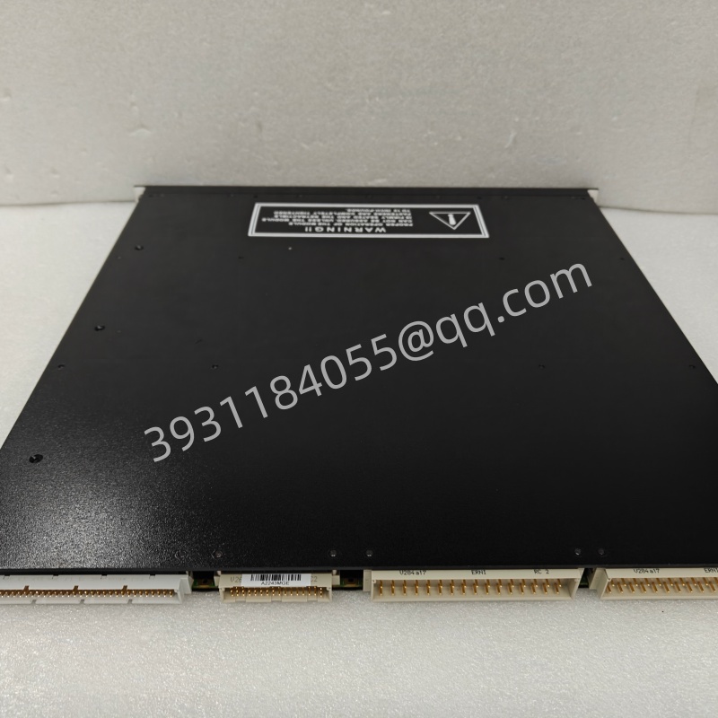
Wiring method:
Usually, detachable terminal blocks are used for easy maintenance and replacement.
Logic power supply (provided by the backplane) and field power supply (external 24VDC, connected to module specific terminals) need to be connected.
3. Indicator light status (panel LED)
The LED on the 3504E panel is the key to rapid diagnosis:
OK/Run: Green constant light indicates that the module is normal; Flashing indicates that initialization or download is in progress; Extinguishing indicates a fault or no power.
Fault: The constant red light indicates a hardware failure or serious error in the module; Flashing may indicate a specific channel malfunction.
Channel LEDs:
Usually, each channel corresponds to one LED.
Bright: indicates that the channel is in an active (conductive) state.
Extinguish: Indicates that the channel is in an inactive (disconnected) state.
Special flashing: In certain fault modes, the LED may flash at a specific frequency to indicate a short circuit or open circuit.
Power: Indicates whether the Field Power is working properly.
3504E vs 3504 (Basic Edition)
Although the two have similar appearances, the “E” version usually has the following advantages:
More detailed diagnostic information: Can provide more specific fault codes in TriStation software (such as distinguishing between short circuit and open circuit).
Higher reliability: Improved circuit design and reduced false alarm rate.
Better compatibility: Better support for new firmware and main processors (such as 3009).
Suggestion: In new projects or spare parts replacement, prioritize choosing 3504E over the old version 3504.
5. Application scenarios
Emergency Shutdown System (ESD): A solenoid valve that controls critical shut-off valves.
Fire and Gas System (F&G): Start the fire pump, open the rain shower valve, and trigger the sound and light alarm.
Process interlocking: Control the start and stop of the pump and the position of the fan baffle.
Auxiliary system: Control non critical but monitored equipment such as lighting and heaters.
6. Maintenance and operation precautions
Hot plug: Supports online hot plug. When the system redundancy is normal (the other two main processors are normal, and there are no serious faults in other modules of this rack), it can be directly replaced.
Note: After replacement, the new module will automatically download configuration from the main processor. During this period, the output status of the module depends on the system configuration (maintaining the last state or entering a safe state).
External power supply:
An independent and stable 24VDC field power supply must be provided for 3504E.
The power capacity needs to be reserved with a margin (recommended at least 1.5 times the load current) to prevent misdiagnosis caused by voltage drop due to startup shock.
Wiring inspection:
Regularly check the tightness of the terminals to prevent looseness from causing excessive contact resistance or heating.
Check cable insulation to prevent short circuits.
Software configuration:
Configure using TriStation 1131.
In the software, it is necessary to correctly set the fail safe direction for each point:
De energize to Trip (DTT): energized during normal operation and de energized during tripping (most commonly used, in compliance with fault safety principles).
Energize to Trip (ETT): Power off during normal operation, energized during trip (special justification required).
Enable or disable specific diagnostic functions (such as open circuit detection) to adapt to on-site load characteristics (some loads may not be recognized by open circuit detection).
7. Common fault handling
Module red light (Fault):
View detailed diagnostic information in TriStation software.
If it is a ‘channel short circuit’, check the on-site wiring and equipment coils.
If it is’ field power loss’, check the external 24V power supply circuit.
If it is an ‘internal fault’, the module may need to be replaced.
Output inactive:
Check if the logic program has output commands.
Check if the power supply voltage is normal.
Check if the external relay or solenoid valve is damaged.
summary
The Triconex 3504E is a mature, reliable, and enhanced diagnostic 16 point TMR digital output module. It is one of the cornerstones for building high security and high availability industrial control systems.
There are no reviews yet.