


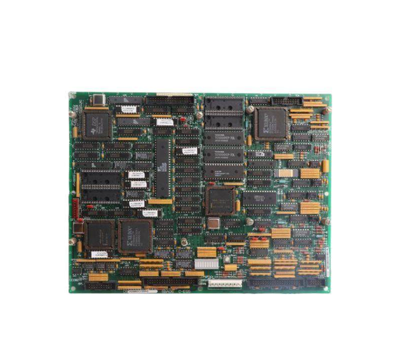
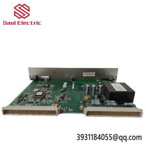
GE DS200SDCCG1A Mark V/VI Gas Turbine Control I/O Communication Card
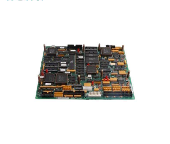
1、 Basic model positioning
Full name: SDCC Drive Control Card Drive Control Motherboard
attribution system
Native adaptation: GE Speedtronic Mark V gas/steam turbine control system
Supporting excitation: EX2000, AC2000, DC2000 generator excitation speed control drive unit
Description: Not natively matched with Mark VI/VIe, only the core control board of the Mark V unit excitation cabinet, integrating three in one functions of driver operation, local I/O, and rack bus communication. It is not just a communication card, but the central processing center of the entire excitation system
Model segmentation DS200SDCCG1A
DS200: Mark V 200 Series Rack Card Family
SDCC: Abbreviation for Drive Control Card Drive Control Board
G1: Hardware version 1 generation; A: PCB silk screen version
Derivative models: DS200SDCCG1ACA/DS200SDCCG1ABA (hardware consistency, firmware batch differences, interchangeable)
Manual Number: GEI-100029 (Original Factory Standard Technical Manual)
2、 Core hardware architecture (three 16 bit parallel processor architecture)
Onboard 3 independent 16 bit microprocessors, operating in isolation and division of labor, without competing for resources, ensuring real-time excitation control:
MCP motor/excitation processor
Execute excitation PID, reactive power regulation, voltage closed-loop, rectifier bridge trigger control, core regulation algorithm calculation
CMP Communication I/O Coprocessor
Responsible for backplane bus interaction, external I/O signal acquisition, fault diagnosis, and upper communication message processing (the I/O communication core unit you mentioned)
DCP Data Diagnostic Processor
Watchdog, fault recording, SOE event storage, over limit alarm, hardware self-test logic
Supporting dual port shared dual port RAM, three CPUs exchange real-time data at high speed without communication delay
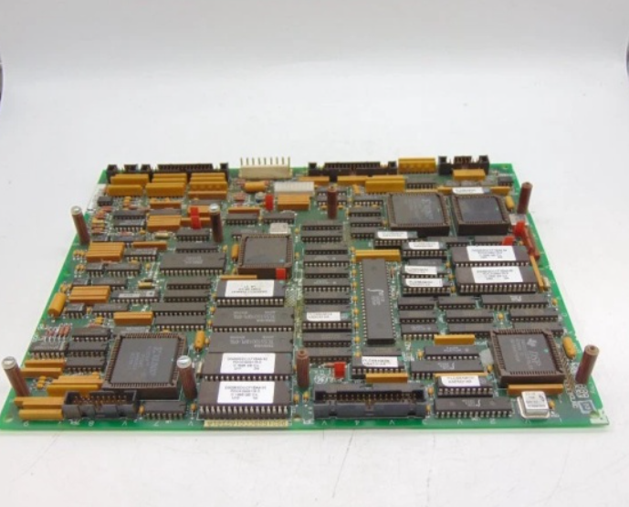
3、 I/O and communication interface (whole machine signal interaction channel)
1. Rack backplane high-speed parallel bus (system communication)
Multi pin European backplane connector enables high-speed data exchange between SDCC and the following Mark V cards:
SDCI power board DS200SDCIG1A (excitation power supply acquisition)
SLCC/LCC logic control card, PSCB power monitoring board
TBC、VCE、 Signal conditioning acquisition card
Bus transmission of excitation settings, valve position feedback, speed, temperature, current and voltage real-time data
2. External I/O terminals (analog+digital signal processing)
Multiple sets of wiring terminals are led out from the board, and the on-site measurement points of the excitation cabinet are uniformly processed:
Analog AI: excitation current, terminal voltage, 4-20mA reactive power/power setpoint, rotor temperature feedback
Analog AO: rectifier triggered control output, reactive power regulation output
Digital DI/DO: excitation switching, demagnetization switch, fan, fault tripping, on-site status hard contact
All signals are equipped with built-in hardware filtering and overvoltage surge protection, suitable for strong electromagnetic environments in power plants
3. External upper level debugging communication interface
Dedicated serial port debugging port: connect to GE Toolbox debugging software, download excitation parameters, record waves, and read fault logs
The rack bus is forwarded to the Mark V system communication card, and the excitation data is forwarded to the DCS and HMI operation stations
Support uploading fault codes and real-time reporting of excitation overcurrent, demagnetization, overvoltage, and rectifier bridge faults
4、 Core function (core of gas turbine excitation system)
Generator excitation closed-loop control
Automatically adjust the terminal voltage, reactive power, and power factor to adapt to the grid connected operation of steam turbine/gas generator sets
Drive power unit control
Output trigger pulse control AC/DC rectifier, drive excitation machine, compatible with EX2000 full series static excitation system
Full channel I/O acquisition and logic interlocking
Collect all temperature, current, and switch status of the excitation cabinet, with built-in demagnetization, overexcitation, underexcitation, and rotor grounding protection logic
Multidimensional communication forwarding
Internally exchange load and speed commands with the Mark V turbine master control; Upload all excitation operating parameters to the external upper system
Hardware fault self diagnosis
Onboard multi-channel status LED indicator lights, real-time monitoring of CPU, RAM, bus, and I/O circuit faults; Fault power outage cache event record for easy shutdown traceability
5、 Key electrical and mechanical parameters
table
Parameter specifications
Power supply backplane DC24V, uniformly supplied by SDCI power board
Processor 3 independent 16 bit MCUs, dual port shared RAM
Working temperature -20 ℃~+65 ℃, installed inside the control cabinet
Storage temperature -40 ℃~+85 ℃
Board size standard Mark V rack full-length board, 19 inch rack slot for direct insertion
Weight approximately 1.2kg
Static protection full board static sensitive components must be replaced with an anti-static wristband
CE certification, industrial safety certification for power plant generation equipment
6、 Typical application scenarios
EX2000 static excitation control system for gas turbine/steam turbine (thermal power, combined cycle power plants)
Excitation regulation and reactive power control of generators in large-scale industrial self owned power stations
Mark V Speedtronic complete set of excitation logic, signal acquisition, communication relay core
7、 Key points for distinguishing and replacing within the same series
DS200SDCCG1A: Basic Standard Edition, General Thermal Power Excitation Cabinet
DS200SDCCG1ABA: Upgraded firmware version, added low load excitation optimization algorithm
DS200SDCCG1ACA: Coating anti-corrosion version, specifically designed for high humidity seaside power plants
Replacement rule: The hardware PCB is fully compatible, and after replacement, the corresponding excitation configuration parameters need to be downloaded through the Toolbox software without changing the external wiring
8、 Key points for on-site use and maintenance
The entire disassembly and assembly process is anti-static, as static electricity can easily damage the MCU and RAM chips on the board
The backplane bus cable needs to be locked tightly, as poor contact can cause excitation communication interruption and voltage fluctuations
Prioritize troubleshooting CMP coprocessor status LED for communication abnormalities, with red light indicating bus/IO channel faults
Not compatible with Mark VI/VIe system, VI series excitation uses DS2100 series new board, cannot be mixed
There are no reviews yet.