


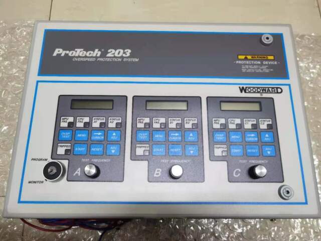
WOODWARD 9907-163 (505 standard type) digital turbine controller complete set of core components
9907-163 belongs to the 505 basic version (without extraction control), and the whole machine is an integrated panel type chassis. It consists of six hardware cores: human-machine interface unit, main control CPU motherboard, switch power board, I/O acquisition driver board, communication board, and whole machine metal chassis; The complete turbine speed control system is composed of peripheral supporting instruments, debugging software, and actuators.
505 overall appearance dimension diagram


Panel installation hole diagram
1、 Chassis shell assembly (whole machine carrier)
Standard panel chassis
Model: Whole machine shell, made of cold-rolled steel plate, NEMA12 standard protection, front embedded installation; Equipped with a left flip lock buckle, the lid can be opened to access the internal circuit board; The bottom two cable threading holes are suitable for instrument cables and power cables.
Optional NEMA4X waterproof and dustproof shell
Installation in outdoor and high humidity dust environments, with the maximum working temperature reduced to 55 ℃, commonly used for on-site control cabinets of steam turbines.
Panel operation window
Front LCD and button sealed window with red hard stop button (independent hardware circuit interruption, not controlled by CPU software).
2、 Front end human-machine interface OCP unit (independent core component)
The front integrated operation panel of the whole machine cannot be separated separately and is the core of on-site operation:
2-line x 24 character backlit LCD display screen
Real time display of speed, valve position, load, alarm, and trip first fault records; Menu based parameter configuration interface.
30 key multifunctional membrane keyboard
Start stop, reset, speed increase/decrease, parameter modification, alarm confirmation, curve retrieval, password locking function.
Hardware emergency stop cut-off button
Passive hard contacts, directly connected to the turbine safety trip circuit, with the highest priority protection.
3、 Main control CPU motherboard (whole machine control core, spare 376-104)
The core of the whole machine operation, adjustment logic, and protection algorithm, 505/505E universal main control board:
Industrial grade 32-bit microprocessor
Built in speed PID speed regulation, load differential/non differential adjustment, automatic speed increase, critical speed avoidance, overspeed protection logic.
Storage unit
Flash memory: stores firmware, unit configuration parameters, and fault event logs; Power off for permanent storage;
RAM operating memory: real-time calculation of rotational speed, analog quantity, and valve position closed-loop data.
Speed signal processing circuit
2-channel MPU magnetic electric probe input conditioning circuit, collects 0.5-25kHz speed measurement gear signals, realizes speed acquisition, zero speed detection, and two out of three overspeed judgment.
Protect logical hardware circuits
The independent hardware overspeed trip channel can still trigger shutdown in case of CPU failure or crash, meeting the safety regulations of the unit.
4、 Integrated I/O signal acquisition and driver board (signal interaction core)
Integrated with the CPU motherboard, all external measuring points, actuators, and relay outputs of the entire machine are processed by this board:
1. Analog input AI (6 channels 4-20mA programmable)
Collect transmitter signals such as unit power, pressure, remote speed setting, oil temperature, exhaust pressure, etc; Built in signal isolation and disconnection diagnosis.
2. Switching digital input DI (16 channels 24VDC)
4-channel fixed functions: start, stop, reset, external interruption;
12 programmable channels: oil switch closing, allowing grid connection, normal oil pressure, external alarm, etc.
3. Analog output AO
2-channel actuator drive output (0-20mA): directly drives the electro-hydraulic converter, servo actuator, and controls the main steam valve of the turbine; Support single valve/split range dual valve control;
6-way 4-20mA transmission output: upload speed, valve position, load to DCS/recorder.
4. Relay output DO (8 SPDT passive contacts, 5A/250VAC)
Unit operation, overspeed trip, alarm, grid connection, fault, and interruption status hard contact output, directly connected to the interlocking circuit.
5、 Switching power board (power core)
Input specifications: DC18-32V wide DC power supply, rated 24VDC, suitable for power plant DC systems;
Multi channel isolated output:
CPU、 Logic circuit 5V low voltage;
24VDC circuit power supply (DI, transmitter circuit);
Driver power supply for actuators;
Communication isolation power supply;
Protection function: overvoltage, undervoltage, short circuit, reverse connection protection, power failure automatically triggers unit interruption alarm.
6、 Communication board (data exchange core)
Onboard multi-channel isolated communication interface, realizing upper level debugging and DCS linkage:
RS232 local debugging port: connect to the 505View software on the computer for parameter download, waveform recording, and fault log export;
RS422 Modbus RTU: interface with DCS and upper monitoring system, upload speed, valve position, alarm, and receive remote settings;
The communication circuit is fully electrically isolated to suppress strong electromagnetic interference in power plants and is designed with shielded single ended grounding.
7、 Complete set of peripheral core supporting components (essential for system assembly)
1. Speed measurement and acquisition components
MPU magneto electric speed probe (passive speed sensor);
Probe shielded coaxial cable;
Speed measuring gear (turbine spindle speed measuring gear disc).
2. Valve actuation components
Electro hydraulic actuator/servo valve (0-20mA drive);
Hydraulic mechanism for hydraulic engine and wrong throttle.
3. Transmitter acquisition equipment
4-20mA pressure, power, temperature, differential pressure intelligent transmitter.
4. Safety interruption circuit accessories
Hardwired circuits for shut-off solenoid valves, emergency shut-off devices, and trip relays.
5. Debugging software tools
505View: upper computer configuration, curve recording, fault record export;
OpView: Remote Modbus monitoring, centralized monitoring of multiple units.
8、 Differences in Core Components between 9907-163 (505 Standard Edition) and 505E (9907-164)
The firmware of the CPU motherboard is different: 505 is only controlled by a single inlet valve; 505E adds extraction/replenishment PID calculation module;
I/O logic resources: 505E expansion auxiliary PID circuit, adapted for pressure regulation of extraction units;
Software function: The 505E supports extraction pressure and load decoupling control, and the hardware circuit board is universal except for firmware differentiation.
9、 Key points for replacing core component failures
The CPU motherboard and power board are separately replaceable spare parts. After replacement, the unit configuration can be downloaded through 505View without the need for on-site re calibration;
The damaged OCP of the human-machine panel can be replaced separately, and the parameters are stored in the CPU flash memory. The panel replacement does not lose the configuration;
Priority should be given to checking the current output channel of the I/O driver board for actuator output circuit faults, distinguishing between line short circuits and board damage.
There are no reviews yet.